In this article, you will learn in details how starting system, starter motor, and starter drive works and troubleshooting diagnosis of the starting system.
Table of Contents
How Starting System Works?
In an automobile, the starting system cranks the engine initially. It has replaced manual effort to crank the engine with the help of cranking rod that was used in ancient days.
Initially, the engine requires cranking, but once the cycle is completed, it starts and runs on its own.
In two-wheeler, it is common to ‘kick start’ the engine, but in recent times a number of manufacturers have introduced ‘button start.’
For initial cranking, an electric motor is provided that gets electric current as input from the battery.
The mechanical energy, in the form of rotation of the shaft, is transmitted to engine. This provides initial movement of crankshaft, connecting rod and piston.
As soon as spark occurs the fuel is ignited, and the output becomes available from the engine. No more cranking is needed, and starting system stops working, and the engine runs on its own.
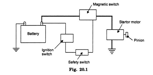
The starting system makes starting of vehicle convenient. A starting system consists of starting the motor, magnetic switch, safety switch, battery, cables, and ignition switch.
These components are connected with each other through two circuits. One is the starting circuit, in which high current flows which is used to start the engine. Second is a control circuit, in which low current flows.
The ignition switch acts as a switch for starting circuits also. In the starting circuit, the current flows from battery to starter motor through a solenoid or magnetic switch. The control circuit connects magnetic switch with battery through ignition switch (Fig. 20.1).
How Starter Motor Works?
The starter motor is like any other electrical motor, but it is designed to work under high electrical overloads and produces very high power. Due to this, the motor can operate for a short duration.
High current is needed to operate it that generates heat. Time is also required to dissipate this heat. Therefore, it is advisable that the motor should be given enough gaps between more than one starting attempts.
The motor has got field coils with pole shoes, armature, and housing that encloses them. Apart from these, it has brushes, bushings that make its operation efficient.
The field coils and pole shoes produce strong stationary electromagnetic fields as current is passed through them.
Magnetic polarity (N or S) depends upon the direction in which the current flows. The magnetic fields produced are opposite in nature.
The armature is located between drive and end frames. It has windings, and the commutator mounted on the armature shaft. The winding is made of a number of coils of a single loop each.
These are insulated from each other and fit into slots in the armature shaft. The commutator has heavy copper segments surrounding the shaft but is insulated from each other and the shaft.
The armature is surrounded by field coils. Current is supplied to the armature, and it produces a magnetic field in each conductor. The magnetic fields are also produced by field coils.
The reaction between these magnetic fields causes the rotation of the armature. The rotation is transferred to the crankshaft of the engine through armature shaft. This causes cranking of the engine.
The current from field coils to the armature is transferred through brushes. These brushes are held with the help of springs against the commutator. The brushes can be from two to six in number for smooth motion and constant torque delivery.
Figure 20.2 represents starting system with all its components.
The field coils produce a stationary magnetic field. The armature windings are placed in this stationary magnetic field, and current is passed through it. A secondary magnetic field is generated.
The lines of forces of the stationary magnetic field move across the winding. They combine on one side and enhance the strength of the magnetic field. On the other side, they are opposed and, therefore, weaken the magnetic field.
There is an unbalanced magnetic force that causes push towards the weaker magnetic field.
Armature windings are in the shape of coils. The current flows in and out in opposite directions. This makes the orientation of magnetic forces in the opposite direction in each segment of winding.
When it is placed in a stationary magnetic field, one part of armature winding is pushed in one direction and the other part in the opposite direction. This causes the rotation of the armature winding.
The winding coil being mounted on shaft causes the rotation of the shaft (Fig. 20.3).
As the armature rotates through half revolution, the flow of current is reversed due to contact between brushes and commutator.
The commutator segment is attached to each coil, and it comes in contact with other brush as it moves past one brush. Thus, the flow of current is maintained in one direction.
The polarity of segments of the rotating armature coil is reversed as it rotates. It is essential that torque rotating the crankshaft is constant, and to achieve this number of armature segments are kept large.
As one segment passes through a secondary magnetic field pole, another segment replaces it immediately. The motors can be series, shunt, or compound type.
The armature is connected in series with field coils and in parallel with field coil in series and shunt motors. In compound motors, it is a combination of series and parallel wiring (Fig. 20.4).
The magnitude of torque from a motor depends upon the current it draws. The motor draws higher current when runs slow. As more torque is needed to crank the engine shaft starting motor requires higher current.
How Starter Drive Works?
Starter drive transfers motion from starter motor shaft to the crankshaft of the engine. It has got a pinion that meshes with a flywheel mounted on the crankshaft (Fig. 20.5).
The flywheel is provided with teeth to mesh with pinion. The meshing of the pinion and flywheel occurs prior to starting of the motor. This is done to avoid any damage to teeth either on the pinion or on the flywheel.
An overrunning clutch is included to protect the starter motor.
After the engine has started, and crankshaft starts rotating at speed higher than that of starting the motor, the armature is disengaged from the flywheel with the help of overrunning clutch.
If not disengaged, the armature would rotate with very high speed (engine speed) that may destroy its winding. The overrun clutch has housing, fixed on armature shaft through internal splines.
Spring-loaded rollers are provided and these wedges tightly against the pinion barrel when forced into their tapered slots.
Pinion and clutch housing are locked together, and this causes the transfer of motion from armature shaft to the crankshaft. When the crankshaft speed goes beyond armature shaft speed, the rollers are released, and pinion gear and armature shaft are unlocked (Fig. 20.6).
At this stage, the pinion overruns the armature shaft until it is withdrawn by starting drive linkage. Starting drive linkage also operates the overrun clutch.
The control circuit has a safety switch that is also known as the neutral safety switch. It prevents the operation of starting system when the transmission is in gear.
Different switches are used for manual and automatic transmissions.
For manual transmission, it is an electrical switch located on the floor (Fig. 20.7). It is operated, and its contacts are closed when the clutch pedal is pressed.
In an automatic transmission, the switch can be electrical or mechanical. In an electrical switch, the contact points are closed when the vehicle is in a neutral position. The switch is located near the gear selector.
The mechanical switch blocks the movement of the ignition key when gears are engaged.
Trouble Diagnosis of Starting System.
The starting system may have troubles such as the engine does not crank or the engine cranks but does not start. Apart from these troubles, the solenoid may have some noise; the pinion may not disengage properly.
To diagnose the trouble, the headlights be switched on and observed. If lights do not dim, and there is no cranking and check whether there is the voltage at the ignition switch and starting motor terminals with ignition key on ‘start.’
If lights dim heavily and there is no cranking the possibility of battery is discharged. If lights dim slightly and no cranking occurs, the pinion may not be engaging properly with the crankshaft.
Also, there may be an open circuit in the starting motor. If lights go out completely and cranking does not occur, there may be an improper connection in the battery.
If there are no lights and cranking also does not occur, the battery is open or dead. If the engine cranks slowly and does not start, it may be due to the defective starting motor.
Solenoid noise may be due to low battery or defective solenoid winding.
That’s all for the working of the starting system, starter motor, and starter drive. Thanks for reaching out here. Please, don’t forget to share it.