In this article, you’ll learn in details that what is anti lock braking system? Components of anti-lock braking system and its types.
Table of Contents
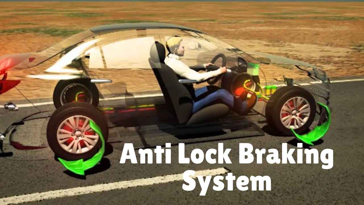
Anti Lock Braking System.
Brakes are an essential controlling device in modern day’s automobiles. Automobiles today can run at very high speed and controlling motion at high speed, mainly when brakes are applied, could cause instability.
At high speed when brakes are applied, the wheels become stationary and they start sliding instead of rolling on the road surface.
As the wheel starts sliding, the steering control is lost, and the vehicle cannot be kept straight. The force of friction is reduced, and that also causes instability.
It becomes difficult for the driver to keep the vehicle straight and the vehicle skids and goes out of control. This situation is dangerous, and an accident can occur.
It becomes essential to keep the vehicle under control when brakes are applied. This is achieved by an anti lock braking system (ABS).
Watch the video below to understand how Anti Lock Braking System works.
Anti Lock Brake System.
When brakes are applied suddenly, the wheels may get locked almost immediately. This causes instability of the vehicle.
If the vehicle is moving on loose snow, the locking of wheels causes the formation of a small wedge in front of the wheel. This helps the vehicle to stop.
This is the only situation where locking of the wheels may be helpful. In all other conditions, it is undesirable.
Pressure Modulation.
To avoid locking of wheels the brakes are applied, and before the wheels are locked, the brakes are released. The same process is repeated several times.
In earlier days, the drivers used to do the same. With the introduction of anti lock brakes system, this is performed by the brake system itself.
Pressing of brakes means building of pressure while releasing the brake pedal means undoing it. This is termed as pressure modulation.
Through the anti lock brake system, modulation of pressure can be achieved even up to 15 times per second. The modulation of pressure maintains the friction between Tyre and road surface and provides stability to the vehicle.
As the sliding of the wheel is avoided, the control on the steering is also not lost, and the vehicle continues to move straight.
Locking of front wheels affects the maneuverability of the vehicle while locking of rear wheels affects its stability. The best results are obtained when the wheels are also allowed to slip in between the application of brakes.
Zero percent slip means the wheel is rolling freely while 100% slip means the wheel is completely locked.
It also means that at zero percent slip the velocity of wheel is same as that of the vehicle and at 100% slip the velocity of the wheel is zero and vehicle is moving at its own velocity.
Due to slip the velocity of wheel is reduced, and the vehicle continues to move with the same velocity. It is termed as slip rate, measured in percent.
For example, if the velocity of the wheel is 30% less than the velocity of the vehicle, it is termed as a slip rate of 30%.
For the anti lock brake system, the ideal slip rate should vary from 10% to 30%. Anti-lock brake systems may differ from each other. These systems could be integral or non-integral.
In integral systems, master cylinder, hydraulic booster and their circuitry are combined together into a single unit.
In the non-integral type of systems, there is a vacuum-assisted booster and master cylinder. Control unit is also a separate unit.
There is a separate hydraulic unit and pump, motor and accumulator. Solenoid valves may be provided to control hydraulic pressure to the wheels.
The anti-lock brake system may further be classified as a single channel or multi-channel systems.
A single-channel system is a two-wheel system when pressure is modulated on both rear wheels at the same time and not to the front wheels. The input is provided to the system from a single-speed sensor that is located centrally.
The sensor may be positioned on the differential unit. The multi-channel system could be two channels, three channels or even a four-channel system.
In a two-channel system again, pressure modulation is applied to two rear wheels only by each channel. There are two-speed sensors for each wheel.
Then there are three-channel systems. These systems have individual circuits for each front wheels and a single circuit for both the rear wheels.
The most effective system is the four-channel system that has independent circuits for all the four wheels. There are separate sensors for each wheel.
In this system, each wheel receives controlled braking action.
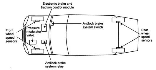
Components of the Anti Lock Brake System.
The design of an anti-lock brake system may vary from automobile to automobile. The modem system has hydraulic and electrical/electronic components.
Apart from components in normal brakes, there are additional components in the anti-lock brake system.
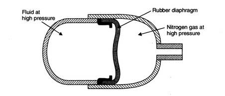
1. Accumulator:
It stores fluid and maintains high pressure in the system. It also provides required pressure for power-assisted brakes. It is charged with nitrogen gas.
It has a diaphragm that separates the two compartments. One compartment accommodates brake fluid at high pressure while others have nitrogen at high pressure.
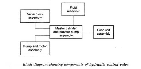
2. Hydraulic control valve:
This valve provides pressure modulation. It builds the pressure in the system when brakes are applied and releases it when the brake is released.
This happens several times during the application of brakes. This valve could be combined with a master cylinder or mounted separately.
In the first case, it is termed as the integral type and in the second case non-integral type. For control, it is provided with solenoid valves.
3. Booster pump:
It provides fluid at high pressure to the anti-lock brake system. It consists of a pump and electric motor, and therefore it is also known as electric pump and motor assembly.
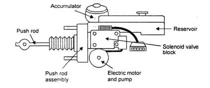
4. Hydraulic unit:
It is an assembly of master cylinder and booster. It modulates the hydraulic pressure in the system with the help of valves and piston.
Fluid at high pressure is also provided through the hydraulic pump for power brakes application.
5. Fluid accumulators:
This temporarily stores the fluid from the wheel cylinder. This fluid is used to build pressure in the brakes hydraulic system. There are two accumulators, one each for primary and secondary hydraulic circuits.
6. Valve:
Antilock brake system module controls this valve. In open position, brake fluid is sent into the master cylinder from booster circuit at high pressure.
This does not allow excessive pedal travel. This is a two-position valve.
7. Modulator unit:
This unit controls the flow of fluid to the individual wheel cylinders. It has a solenoid valve that controls a number of other valves that control the fluid flow.
The unit also has relays that are activated by the control module and control operation of solenoid valves.
8. Solenoid valves:
These are located in the modulator. Control module transmits signals that operate these valves. These are switched on and off to control the hydraulic pressure in different wheels.
The solenoid valves for different wheels are located together in an assembly attached to the side of the master cylinder. The block is connected to the anti-lock brake system control module.
9. Wheel circuit valves:
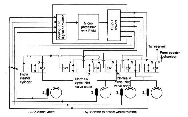
The two circuits are controlled individually by separate solenoid valves. One is meant for controlling the inlet valves and others for controlling the outlet valves.
The pressure in the circuit is increased, decreased or maintained at a steady level by using the inlet and outlet valves. The control module determines the operation of the individual valve.
The control module for the anti-lock brake system provides an electric supply of 12 volts that operates the solenoid. The circuits are not operated during normal driving.
Apart from these components, the system has some electrical and electronic components also. These components make the system more dependable but at the same time, complex and costly.
10. Control module:
It is a small electronic unit consisting of a microprocessor. The microprocessor is programmed and executes instructions according to program.
It is a small unit which can be mounted to a master cylinder or hydraulic control unit. It is given inputs from sensors to monitor wheel speed and from the hydraulic unit.
It can diagnose and rectify problems on its own. It monitors the proper operation of the anti lock brake system.
11. Brake pedal sensor:
This sensor is a switch. When the brake pedal is pressed beyond a particular limit, the switch opens and turns on the pump motor.
This fills the hydraulic reservoir with fluid at high pressure, and the brake pedal is pushed. The push continues till the switch is closed again.
This switches off the motor and pushing of the pedal stop.
12. Pressure switch:
This switch indicates low pressure through a warning light on the dashboard. The switch activates the pump motor when pressure is reduced below the designed level.
When designed pressure is attained, the switch again operates and pump motor is stopped.
13. Pressure differential switch:
This switch transmits a signal to control module when higher than designed pressure difference occurs in the system. The switch is inside the modulator.
14. Relays:
These are used to switch on the motors and solenoids. These require a low current signal to operate, and that is provided by the control module.
These are electromagnetic devices.
15. Toothed ring:
This wheel is provided with teeth that pass by the wheel speed sensor. As this happens, the AC signal is generated. The signal fades away as the tooth moves away.
The next tooth that passes by the sensor causes the generation of the signal. This way, the pulsing signal is generated. This is sent to the control module.
The control module converts it into the wheel speed. The ring is located on the axle shaft.
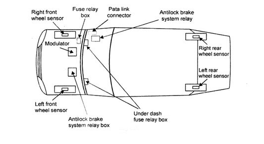
16. Wheel speed sensor:
This sensor is in the form of a coil with a permanent magnet in the center. It sends the pulsating AC signal generated by a toothed wheel to the control module.
The system is provided with indicator lights also. These lights act as warning lights in case there is some fault in the anti-lock braking system.
Also, there may be another warning light to indicate a fault in the basic brake system.
Apart from these components, the system has a Data Link Connector that acts as a mean to operating conditions, other information about the automobile and diagnostic information.
To diagnose the fault in the system, numeric identities are provided to different faults. These trouble codes are fed to the control module.
Types of Anti lock Braking System.
1. Non-Integral Anti Lock Brake Systems.
In the non-integral type of systems, there is a vacuum-assisted booster and master cylinder. Control unit is also a separate unit.
There is a separate hydraulic unit and pump, motor and accumulator. Solenoid valves may be provided to control hydraulic pressure to the wheels.
i. Two Wheel System:
These systems have pressure modulation in rear wheels only. As brakes are applied, the pressure is transmitted through valves. The control module monitors the speed sensor signal.
If it finds that deceleration caused is high and may cause locking of wheels, it activates the isolation valve. This stops the building up of pressure on rear wheels that prevent further deceleration.
If still the deceleration is not prevented, the control module would activate the dump valve. This continues until the deceleration of the wheel, and the vehicle becomes the same.
When the brake pedal is released, the control module deactivates the isolation valve. This allows the fluid to go back to the master cylinder.
The control module also controls the solenoid valve. The control module also detects errors in the system. The wheel speed sensors feed the wheel speed to control module continuously.
If the automobile is a four-wheel drive with an option of two-wheel drive, the anti-lock brakes system stops functioning, when the operation is shifted to four-wheel drive.
ii. Four-Wheel System:
In this system, there are four channels, one for each wheel. The hydraulic control unit has two solenoid valves for each wheel.
Normal braking is assisted by the vacuum-power brake system. In another variant, there are three channels, one each for front wheels and one for both rear wheels.
The system has two solenoid valves for each channel. Better steering control is available in these systems.
The modulation of pressure occurs in all the four wheels which make the operation of brakes very safe, and automobile can be stopped in the shortest possible distance.
The control module closes the inlet solenoid valve when it senses that due to deceleration, the wheel may lock up. This does not allow further entry of fluid in the circuit.
If the wheel still decelerates and there is the possibility of lock-up, the control module opens the outlet solenoid valve. After the brakes are released, the control module brings back the inlet and outlet solenoid valves back to the original position.
The control module also calculates the slip rate of each wheel through wheel speed sensors. If the slip rate is high, it transmits a control signal to modulator.
Modulator:
The modulator consists of inlet and outlet solenoid valves, reservoir, pump and motor. The callipers are relieved of fluid pressure.
There are three control modes, namely decreasing the fluid pressure, holding the fluid pressure and increasing the fluid pressure.
The first mode where fluid pressure has been decreased the inlet solenoid valve is closed, and the outlet solenoid valve is open.
The callipers are relieved of fluid pressure as existing fluid in the calliper flows back to master cylinder through an outlet solenoid valve.
When fluid pressure is increased, the fluid at high pressure is pumped to callipers. The inlet solenoid valve is open, and the outlet valve is closed.
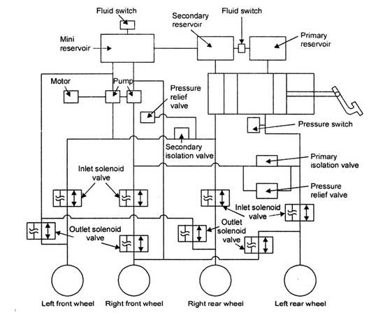
In the third mode, when fluid pressure is retained, both the inlet and outlet valves are closed. The pump provides excess fluid needed during anti-lock operation.
The fluid is released to accumulator afterwards that acts as a temporary store for it. After the operation, the pump drains the accumulator.
An electric motor drives the pump. The motor is controlled by the control module. The pump is required to redirect the fluid quickly as the solenoid valves open and close rapidly.
The anti lock braking system is self-monitoring. If some component does not perform properly, it is indicated to the driver through a warning light.
However, the normal application of brakes continues if the anti-lock braking system develops some fault.
2. Integral Anti-lock System.
In integral systems, master cylinder, hydraulic booster and their circuitry are combined together into a single unit.
i. Four-Wheel System:
Upon applying brakes, the deceleration of each wheel is monitored by the control module. If the deceleration is high and is likely to cause locking of wheel, the signal is transmitted to the hydraulic unit.
The hydraulic unit initially keeps the fluid pressure at the wheel constant, and it is not allowed to increase. If still, the deceleration remains high, the fluid pressure is reduced.
This is achieved by control module by transmitting a signal to a solenoid valve that actuates the hydraulic unit. This prevents the locking of wheels during application of brakes.
On the other side, if the braking effort is not sufficient, the control module transmits a signal to the hydraulic unit and the fluid pressure is increased, thereby increasing the braking effort.
This control cycle is repeated many times depending upon the requirement of brake action.
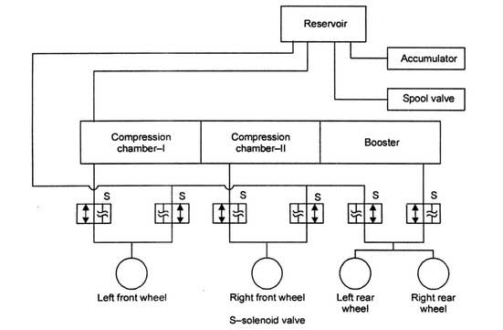
Once the brake pedal is released, the piston in the master cylinder moves back, the fluid from the booster chamber flows back to the reservoir. When the brakes are applied under normal conditions, the pushrod operates a lever.
This moves the spool valve, and port between the booster chamber and reservoir is closed. It also opens the port from the accumulator partially.
The opening of the port is in proportion to the force applied on the brake pedal. The fluid at high pressure moves from accumulator to booster chamber.
The fluid pushes the piston forward and adds to the thrust on the pushrod. When the control module detects that wheels are locking it opens a valve.
The valve supplies the fluid to chambers between pistons in the master cylinders and between the retraction sleeve and piston in the first master cylinder.
The fluid at high pressure on the retraction sleeve forces the pushrod and brake pedal back. In fact, fluid at high pressure is being supplied by accumulator and not through brake pedal action.
The control valve also opens and closes solenoid valves to control the brake action on wheels.
When solenoid valves are open, the pistons in master cylinders provide fluid to the front wheels and booster chamber provides fluid to rear wheels.
When these are closed, the master cylinder and booster chambers are cut of. The fluid returns from wheels to the reservoir.
While cornering, the brakes are applied and anti lock brake system has to work differently in this situation.
The control module operates under different programming. A switch gives an indication to the control module about the application of brakes while cornering.
ii. Automatic Traction Control:
An automobile may lose its track in some situations such as accelerating on a wet surface. This creates instability for the vehicle and may be dangerous for the occupants.
In four-wheel drive and front-wheel driven vehicles, if traction is lost on one wheel, it could cause the vehicle to go out of control.
An automatic traction control system applies the brakes whenever the vehicle tends to lose the track.
In a front-wheel-drive vehicle, if automatic traction control is provided, the three-channel anti-lock brake system is incorporated whereas, in rear-wheel drive and four-wheel drive vehicles, four-channel anti-lock brake systems are incorporated.
It is essential that the rotary speed of the wheel is in proportion to the vehicle speed. If the rotary speed of the wheel is more than vehicular speed, it is termed as ‘slippage’ and causes the loss of traction.
Normally, a slippage of 10% is permissible.
The control module in the automatic traction control system monitors the wheel speed through the sensor.
If the loss of traction is sensed due to the increase in the rotary speed of a particular wheel, control module signals the opening/closing of solenoid valves causing the application of brakes to that wheel.
The control module and hydraulic valve unit may be different for the automatic traction control system and anti lock brake system.
In some cases, the two systems may use a single control module and hydraulic unit.
Some automatic traction systems are meant for wet or snow-covered roads. These systems operate only at low vehicular speeds.
Some automatic traction control systems also control the functions of the engine and work at high vehicular speeds.
The functions of the engine that are controlled include ignition timing and partially closing the throttle. Even fuel supply to one or more engine cylinders can be cut to reduce the vehicular speed for better traction control.
The indicator is provided on the dashboard to the intimate driver that the automatic traction system is operating.
iii. Automatic Stability Control.
When the vehicle is moving on the curved path, it may be under-steer or over-steer.
In the case of ‘under-steer,’ the vehicle tends to move the curved path inwards, and it moves the curved path in case of ‘over-steer’ outwards.
Stability control systems can provide stability to the vehicles in these situations and cause desired corrective actions also.
In case of over-steer, the outside front brakes are applied and in case of under-steer inside rear brakes are applied. The system uses the steering angle and speed of the four wheels to calculate the correct path.
It also senses the lateral forces and vehicle yaw to calculate the actual path followed by the vehicle.
Yaw is the natural tendency of the vehicle to rotate about its vertical axis. If the two paths differ, it applies the corrective measures through the application of brakes.
That’s all for the Anti Lock Braking System. I hope you like it. Please, don’t forget to share it.
Thanks!
Brilliant article which has answered in some detail whether my previous thoughts were correct regards the wheel sensor operation and how they function to supply a feed back signal to the brain box of the system, Am I right in thinking the wheel sensor is a magnet used to generate the AC current as in an AC electric generator