Belts and pulleys transmit power with some slippage. If this slippage cannot be tolerated, gears are used.
In this article, we will discuss the Gears, Gear Drives, Types and Classification of Gears, Gear Terminology, its advantages, and disadvantages.
So, Let’s get started.
See Figure 4.1(a) in which two wheels, A and B, are mounted on parallel shafts and are made to touch. Now, if A is rotated in an anticlockwise direction, wheel B starts rotating in a clockwise direction due to friction at their periphery.
If a slight load is put on the driven shaft, the wheel starts slipping. To avoid this slipping, teeth are cut on their periphery, and such a wheel is called gear, as shown in Figure 4.1(b).

Speed can be increased or decreased by selecting the diameters in the proportion of speed reduction. Gear ratios (driver to driven speed ratio) up to 5 are common.
Gear is never used alone but always used in pairs; one is called driver gear and the other driven gear. The size depends on the power to be transmitted and center distance between the shafts.
A gear of small diameter is called pinion, whereas a gear of infinite diameter is called a rack; that is, it is straight, as shown in Figure 4.1(c).
For speed ratio more than 5, gear trains or worm gears are used. A gear is a circular wheel having teeth on its periphery. The teeth may be external, as shown in Figure 4.2(a), or internal, inside a ring shown in Figure 4.2(b).
The gear with internal teeth is called a ring gear or an annular gear. The direction of rotation of both the gears is the same.
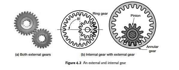
Table of Contents
Gear Drives versus Other Drives;
Drives are used to transmit power from one shaft (generally of a prime mover) to the other shaft. The prime mover may be an engine or an electric motor, etc. It may run at speed different from the speed required for the machine.
Hence, a drive is used to transmit power and, at the same time, reduce or increase the speed as required by the machine.
Many types of drives are used, such as a belt and pulleys, chain and sprockets, and a gear set.
Gear drive vs. other drives are discussed as under:
1. Belt drive slips, whereas gear drive does not slip and offers a positive drive.
2. Chain drive does not slip, but there is a slight speed variation in the driven shaft speed depending on the number of teeth of the driver sprocket, whereas in gear drive, there is no speed variation. Speed is constant for any number of teeth.
3. Belt and chain drives are preferred if the center distance between the shafts is more, whereas gears are not suitable for large center distances.
4. In belt drive, if there is any locking on the driven shaft, it starts slipping and acts as a fuse, whereas in gear drive, the teeth may break.
5. Belts do not transfer the driver shaft shocks, whereas, in gear drives, shocks are also transferred.
Advantages and Disadvantages of Gear
Advantages of Gear;
1. Gears can be used for small to large powers.
2. The drive is positive and gives an exact velocity ratio.
3. Transmission efficiency is high.
4. Offers reliable service.
5. Maintenance is inexpensive. If properly lubricated, these drives offer the longest service life in comparison to other drives.
6. Occupies less space, hence compact design.
Disadvantages of Gear;
1. Suitable for small center distances only.
2. Costly due to special tools required for manufacturing.
3. Can cause vibrations due to error in manufacturing.
4. Requires proper lubrication for satisfactory working.
Types of Gear
Gears are of many types. These are classified according to the inclination of their teeth as follows.
1. Spur gears;
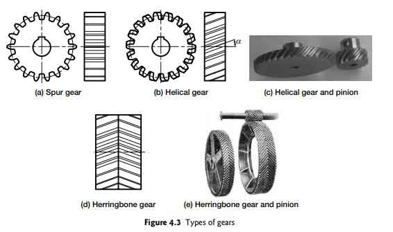
Spur gear drive is the simplest type of drive and is most commonly used. They have straight teeth, whose axis is parallel to the axis of the gear [See Figure 4.3(a)].
2. Helical gears;
Helical gears have their teeth inclined at helix angle α, as shown in Figure 4.3 (b and c). Owing to this inclination, these gears give rise to axial thrust.
This thrust can be canceled using double helical gears called Herringbone gears, as shown in Figure 4.3 (d and e).
3. Bevel gears;
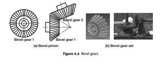
Bevel gears are used, where power is to be transmitted at an angle. The gear blank takes the form of a cone’s frustum instead of a cylinder (Figure 4.4).
The thickness of teeth and height also decreases towards the center. All teeth point towards the center.
4. Worm and worm wheel
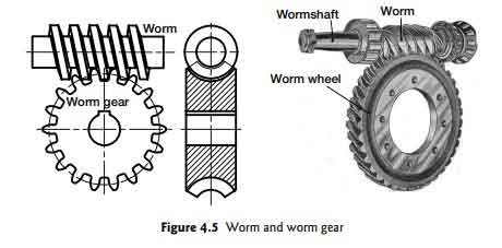
Worm and worm gears are used when large speed reduction is required. A ratio of up to 20 or even more can be got in one stage only.
The worm is in the form of a threaded screw of the trapezoidal section, with a large pitch that matches the worm wheel with mating grooves of the same profile (Figure 4.5).
Gear Terminology
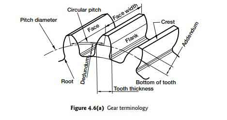
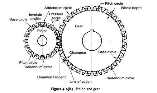
The following terms used for gear are shown in below Figure 4.6:
Pitch circle diameter:
An imaginary circle on which rolling takes place without slip. This diameter is called pitch circle diameter (D) in short PCD also.
(Dp) means pitch circle diameter (PCD) of the pinion.
(Dg) pitch circle diameter (PCD) of gear.
Addendum (a):
Radial distance from the tip of the tooth to PCD.
Dedendum (d):
Radial distance from PCD to root of the tooth.
Addendum circle (Da):
Outermost circle diameter Da = D + 2a.
Dedendum circle (Dd):
Circle passing through the roots of teeth D = D − 2d.
Base circle (Db):
Imaginary circle on which involute tooth profile is generated (See Section 4.10)
Circular pitch (Pc):
Arctual distance from center to center between two adjacent teeth at PCD. pc = π D / z, where z is the number of teeth.
Diametrical pitch (Pd):
Ratio of the number of teeth z to PCD, pd = π D / z, where z is number of teeth.
Module (m):
Ratio of PCD to the number of teeth, m = D / z.
Whole depth (h):
Radial depth of tooth, addendum + dedendum, h = a + d.
Working depth:
Distance up to which tooth mates with another gear = 2a.
Clearance (c):
Difference between whole depth and working depth, c = d − a.
Tooth thickness (t):
Thickness of tooth at PCD, t = pc / 2.
Backlash:
Gap between tooth space and tooth thickness along pitch circle.
Top land:
Surface at the tip of the tooth along the addendum circle.
Crest:
Outermost periphery of the tooth at the tip.
Face:
Curved surface of the tooth above the pitch circle up to its tip.
Flank:
The Curved surface of the tooth below the pitch circle up to the root.
Face width (b):
Width of the gear along the axis of the shaft.
Root radius (r):
Radius at the bottom between the tooth flank and the root circle.
Pitch point:
Common point between two pitch circle diameters of gear and pinion.
Pressure angle:
Angle between a line tangent to the base circles and common normal to the two gears at the contact point.
Standard pressure angles are 14.5°, 20°, and 25°.
Path of contact:
Path traced by the contact point, from beginning to end of contacting of teeth.
Arc of contact:
Path traced by a point on pitch circle, from beginning to end of contacting teeth.
Arc of approach:
Portion of the path of contact from beginning to the pitch point.
Arc of recess:
Portion of the path of contact from pitch point to the end of the engagement.
Contact ratio:
It is the ratio of the arc of contact to circular pitch. It indicates the number of teeth in contact.
That’s all for the gear terminology, types, advantages and disadvantages. I hope you like it. Please, don’t forget to share it.
Thanks!